



Detailed configuration
KVM
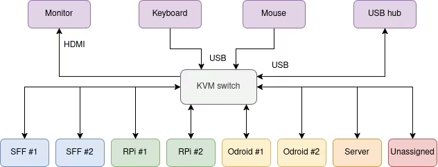
The KVM switch doesn't require any special preparations. Simply install the L-shape mounting brackets and the four bolts.
We do not currently use the IR receiver or the serial interface for controlling the KVM switch.
The HDMI/USB outputs are connected to the monitor installed on the desk. The HDMI/USB inputs are connected to the devices with video and USB connections.
Our KVM switch has the following configuration
- Output: left monitor
- 1: SFF #1 (controller)
- 2: SFF #2
- 3: Odroid #1 (odroid)
- 4: Odroid #2 (odroid2)
- 5: RPi #1 (raspi1)
- 6: RPi #2 (raspi2)
- 7: x86 server
- 8: x86 desktop / legacy x86 PC
The right monitor is directly connected to SFF #1 or the x86 desktop PC (multi-seat).
Routers
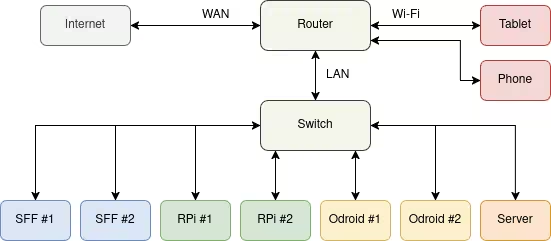
The routers can be configured to operate as Wi-Fi clients, access points (AP), or bridges. The Wi-Fi modules can also be powered off to use the units as simple wired Ethernet routers. There is some room for small foot-print services such as MQTT. In general, the routers are just general purpose computers with an integrated, programmable ethernet switch, (possibly accelerated) firewall, and Wi-Fi cards that also operate in AP mode.
One of the routers is used by default to isolate the University's LAN (or one other public network) from the internal lab network. The default configuration of OpenWRT is suitable for connecting to wired corporate networks.
Our routers have the following configuration:
- Router 1 (Asus)
- OS: OpenWRT
- WAN -- corporate network
- LAN1 -- switch 1
- LAN2--4 -- disconnected
- USB -- broken!
- Wi-Fi: 5 GHz 802.11ac, WPA2/3, powerlab
- Router 2 (Asus)
- OS: OpenWRT
- WAN -- disconnected
- LAN1-2 -- disconnected
- BRIDGE1-2 -- Wi-Fi bridge
- Wi-Fi: 5 GHz 802.11ac, WPA2/3, WDS AP, powerlab2
- Router 3 (Asus)
- OS: OpenWRT
- WAN -- disconnected
- LAN1-2 -- disconnected
- BRIDGE1-2 -- Wi-Fi bridge
- Wi-Fi: 5 GHz 802.11ac, WPA2/3, WDS client, powerlab2
- Router 4 (TP-Link Archer C7 2.0)
- OS: OpenWRT
- WAN -- disconnected
- LAN1-4 -- disconnected
Meters
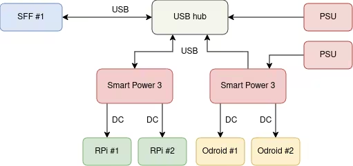
Before assembling the meters, the rack shelf needs to be modified in order to fit all the meters and the USB/DC cables. In our setup we used a Dremel tool to cut off a piece of metal (width ~1 cm) from the right side of the shelf. This way the last USB cable can extend a bit outside the rack shelf. This modification might not be necessary if the DC and USB cables don't use too much space horizontally.
All the cables need to have a 90° angle. Cables from different brands differ in their dimensions. At least the Ugreen 90° angled USB cables are perfect for this setup. For the DC cables, quite many of the 90° angle adapters might be too wide. On the other hand, many pre-kassembled DC connectors with cables have very thin wire gauge, which can affect the stability of the meters.
Our meters have the following configuration:
- SmartPower 3 #1
- Switch #1
- Switch #2
- SmartPower 3 #2
- Odroid #1
- Odroid #2
- SmartPower 3 #3
- RPi #1
- RPi #2 / Router #3
- SmartPower 3 #4
- Router #1
- Router #2
Switches
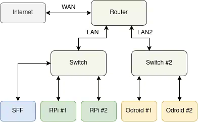
The non-managed Linksys switches do not have any accessories for mounting them anywhere. We suggest mounting them vertically with strong two-sided tape. The bottom unit could also be mounted with bolts if there are holes on the shelf.
We disassembled the cases, inserted a backplate with bolts and connected this to the shelf with another set of bolts. The backplate needs to be thick enough so that it cannot bend. The cases need to be disassembled before drilling.
The DC input is fed from the power meters, which allows the power measurement of network traffic and devices.
The managed switch unit does not require any special preparations. Simply install the L-shape mounting brackets and the four bolts.
Our switches have the following configuration:
- Switch #1
- Connected to LAN on Router #1
- Connected to all SUTs
- Powered by SmartPower 3 #1
- Switch #2
- Connected to LAN on Router #1
- Powered by SmartPower 3 #1
- Managed switch
- Connected to WAN on Router #1
- Connected to corporate network
- Powered by AC
- Switch #3 (4-port)
- Disconnected
- Powered by SmartPower 3 #4
Cable management
The cable management unit with the hole and the brush does not require any special preparations. Simply install the four bolts. This unit can be used for routing cables ( mostly DC and Ethernet) between the front and back of the rack.
Small form-factor PCs
The small form-factor PCs have four threaded holes at the bottom. The four holes form a square with the vertical/horizontal distance of 100 mm between the holes. We drilled similar holes to the rack shelf and secured the machines in place with four M4 bolts. There is a M4 nut between the shelf and the enclosure. This serves two purposes - to lift the machine a bit and make it easier to press the power button, and to prevent the bolt from going too deep inside the enclosure.
Our SFFs have the following configuration:
- SFF #1
- OS: Arch Linux rolling release
- Runs PowerGoblin instance
- Powered by AC
- SFF #2
- OS: Windows 10
- Powered by AC
Storage box
The front panel of the storage case comes with the necessary plates for mounting the case to the rack. Keep the key in a safe location.
Our storage box has the following configuration:
- Ethernet cables
- USB cables (mini, micro, USB-C, adapters, USB-DC)
- Adapters: USB-ethernet, HDMI-DP
- Dupont cables
- Banana to 5.5mm DC cables
- Banana to banana cables
- Electric tape
Server PC
The front panel of the ATX PC case comes with the necessary plates for mounting the case to the rack. Since the case is rather heavy, it helps if another person can help with the assembly.
We removed the noisy case fan and replaced it with a 120 mm version, installed on the front panel.
Our server PC has the following configuration:
- OS: Arch Linux rolling release
- Docker, collectd, ...
- Powered by AC
Desktop PC
The desktop PC currently has Geforce 1070 and Radeon RX 5500 XT 8GB installed.
Our desktop PC has the following configuration:
- OS: Arch Linux rolling release
- Docker, collectd, ...
- Powered by PMD2
Odroid
The devices support detachable DDR4/5 and M.2 modules that are commonly used in laptop computers. When assembling, one of the screws is dangerously close to the resistors on board. Powering the device with this resistor missing can brick the whole board.
Our Odroid PCs have the following configuration:
- OS: Arch Linux rolling release
- Docker, collectd, ...
- Powered by SmartPower 3 #2
Raspberry Pi
Small TFT screens can be connected and powered via the Raspberry Pi board, HDMI monitors via HDMI connectors.
The Raspberry Pis can be powered either via GPIO pins (unsafe) or via USB-C. There are useful USB-C to 5.5mm DC plug adapters for connecting the devices.
Our Raspberry Pis have the following configuration:
- OS: DietPi
- Powered by SmartPower 3 #3
Mobile devices
Mobile phones, tablets, and other low-powered mobile devices. Can be either powered directly by replacing the battery or by charging a fully charged device. Unfortunately the battery management typically affects the readings and decreases accuracy.
Our mobile devices have the following configuration:
- OS: Android, Arch Linux (x86-64 tablet)
- Powered by SmartPower 3 #4
Next step: Summary of the parts
The next hardware section covers the Summary of the parts.