



- Measurement technologies and meter hardware
- Next step: Software-Based Meters and Measurement software
Measurement technologies and meter hardware
This section examines the characteristics and suitability of physical measuring devices suitable for energy measurement in information technology.
This section looks at the equipment used for measurement. The first section looks at the physical principles that are used internally by the different types of meters. The second section provides a classification of the various off-the-shelf measurement products according to their principle of use. The following sections list the complete meters, measurement modules and individual integrated circuits found in the study.
The results of the analysis can be used to support the purchase of ready-made commercial measuring devices. Although the models available for sale and the prices change over time, the analysis identifies various types of devices for which this material can be used in procurement and use. We have also assessed the suitability of the devices for use in a measurement laboratory and with the appropriate software (PowerGoblin).
Measurement technologies
Electrical power and energy measurements are fundamentally based on observing the flow of electrical charge through a system. Instantaneous power is obtained by multiplying voltage and current, while energy consumption is determined by integrating power over time. Consequently, the accuracy of an energy meter depends not only on the quality of the current sensor but also on voltage measurement, timing precision, synchronization, and signal processing.
In practice, most measurement instruments determine energy consumption by measuring current using one of several physical principles. The simplest approach is direct measurement of the voltage drop across a known resistance. Alternative methods exploit the magnetic field generated by electric current, electromagnetic induction, optical effects, or magnetoresistive phenomena.
A less common but sometimes useful approach is indirect energy measurement, where a device is powered from an energy storage element such as a battery or capacitor with known capacity. By measuring the change in stored energy before and after operation, the consumed energy can be estimated. Such methods are generally less precise for dynamic workloads but can be useful for long-duration experiments or isolated systems.
Different sensing technologies exhibit trade-offs in accuracy, bandwidth, isolation, cost, power dissipation, and ease of integration. No single technique is universally optimal, and the selection of measurement technology depends on the characteristics of the system under test.
| Technique | AC | DC | Description |
|---|---|---|---|
| Physical sensing principles | |||
| Shunt resistor | X | X | The most widely used current measurement technique in low-voltage electronics. Current is measured indirectly from the voltage drop across a precision resistor according to Ohm's law. Shunts provide excellent linearity, bandwidth, and low cost, making them common in integrated power monitors and laboratory instruments. Four-terminal (Kelvin) shunts are often used to minimize contact resistance errors. Maximum continuous current for shunts is typically 66% of the peak max. |
| Hall-effect sensor | X | X | Measures the magnetic field generated by current flowing through a conductor. Hall sensors provide galvanic isolation and can measure both AC and DC currents without inserting a resistive element into the power path. They are widely used in power supplies, motor drives, and battery management systems. |
| Fluxgate / zero-flux sensor | X | X | High-precision magnetic sensors that actively compensate for magnetic flux to maintain zero magnetic field in the sensing core. These devices provide excellent accuracy, linearity, and low offset drift, making them common in laboratory-grade power analyzers. |
| Current transformer (CT) | X | Uses electromagnetic induction to measure AC current through a transformer core. CTs provide electrical isolation and are suitable for high-current and high-voltage systems but cannot measure DC currents. | |
| Rogowski coil | X | An air-core coil that measures changing magnetic fields generated by AC currents. Rogowski coils offer very wide bandwidth and do not saturate like iron-core transformers, making them useful for transient measurements and high-current applications. | |
| Fiber-optic current sensor (FOCS) | X | X | Measures magnetic fields through optical phenomena such as the Faraday effect. These sensors provide excellent electrical isolation and immunity to electromagnetic interference, making them suitable for power grid and high-voltage applications. |
| Magnetoresistive sensor | X | X | Uses changes in resistance caused by magnetic fields. Technologies include AMR (anisotropic), GMR (giant), TMR (tunnel), CMR (colossal), and EMR (extraordinary). These sensors can offer higher sensitivity than Hall sensors and are increasingly used in compact, low-power applications. |
| Capacitive current sensor | X | Capacitive current sensors measure electrical current indirectly through the electric field generated by a conductor rather than its magnetic field. These sensors exploit capacitive coupling between conductors and can provide galvanic isolation without requiring direct electrical contact. Capacitive sensing is primarily used in high-voltage applications where conventional current transformers or magnetic sensors may be impractical. | |
| SQUID sensor | X | X | Superconducting Quantum Interference Devices (SQUIDs) are among the most sensitive magnetic sensors currently available and are capable of detecting extremely small magnetic fields generated by minute electrical currents. SQUID sensors exploit quantum mechanical effects in superconducting materials to achieve sensitivity far beyond conventional magnetic sensing technologies. |
| Calorimetric measurement | X | X | Calorimetric measurement determines energy consumption by measuring the heat dissipated by a device rather than directly measuring electrical quantities. Since nearly all consumed electrical energy is eventually converted into heat, calorimetry can provide an absolute reference measurement independent of the electrical properties of the system under test. |
| Integrated measurement technologies | |||
| Coulomb counter / power monitor IC | X | Power monitor ICs combine precision analog front-ends, AD-converters, and DSP logic into a single component for measuring voltage, current, power, and energy consumption. Most devices employ an internal or external shunt resistor to measure current and digitally integrate the measured current over time to estimate charge transfer (coulomb counting) or energy consumption. These devices are widely used in battery management systems, mobile devices, embedded systems, and low-power electronics due to their compact size, low cost, and digital interfaces such as I²C or SPI. | |
| Energy metering IC | X | (X) | Specialized devices designed for accurate measurement of electrical parameters in power analyzers and smart electricity meters. Typically combine high-resolution AD-converters with dedicated DSP capabilities for calculating RMS voltage and current, active and reactive power, power factor, and accumulated energy consumption. Generally require external voltage and current sensors, such as shunts, current transformers, or Hall-effect sensors. They are optimized for AC measurements and often support multi-phase power systems, harmonic analysis, and standardized billing applications. |
| Technique | Examples | Suitability | Downsides |
|---|---|---|---|
| Shunt resistor (#1) | TME | Low current, low-cost designs | Additional resistive load, accuracy of the resistor value, thermal drift |
| Hall sensor | Mouser | Low-cost designs | Magnetic interference |
| Fluxgate / zero-flux sensor | Hioki, Mouser | High accuracy, resolution & bandwidth | High sec power consumption, noise |
| Current transformer | TME | High voltage & current | Saturation, hysteresis, phase shift errors (power and energy meters) |
| Rogowski coil | TME | High bandwidth signal | Requires integrator circuit |
| Fiber-optic current sensor | ABB | Power grid | Size, price |
| Magneto-resistive current sensor | Digikey | Non-linear behavior, thermal drift, sensitive to external fields | |
| Coulomb counter / power monitor IC | TI | Batteries, mobile devices, embedded systems | Limited range, calibration required |
| Energy metering IC | Smart meters, power analyzers | Requires external sensors | |
| Capacitive current sensor | High voltage | Limited applicability to low-voltage systems, specialized | |
| SQUID sensor | Ultra-low current measurement | Cryogenic cooling | |
| Calorimetric measurement | Absolute validation | Slow, complex |
Classification of off-the-shelf power meters
In the study of measurement equipment, the meters were classified into the following categories:
- AC meters
- Measuring power supply units (PSU) with integrated measurement
- Meter modules requiring an external PSU
- DC supply connected meter
- USB power meter
- Component modules (circuit boards. ICs) and
- Built-in meters
AC meter
An AC meter is the simplest to use - the meter is connected between the power outlet and the device to be measured, either with the electricity passing through the meter or with the meter mounted around the power cable (possible to install without shutting down the device). An AC meter is also suitable, for example, for data centers where complex or custom wiring is not possible. AC metering is very suitable for measuring a wide range of equipment, as most IT devices can be supplied with AC power (even battery powered devices). There are also special AC meters for very high voltage and current environments such as power grids. There is a wide selection of measurement technologies for AC.
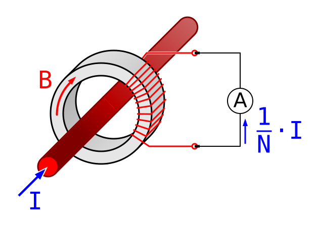
AC meters need to support measurement over a relatively wide range of currents, as the consumption of devices and equipment differs significantly. Low-cost AC meters may not be able to measure the highest power devices and may have other sorts of limitations. For example, the power factor of the switching power supplies makes the measuring less straightforward compared to purely resistive loads, the different capacitor stages in the system behave as a buffers, adding latency and smoothness to the results. The measurement focuses on the total consumption of the whole system, which also makes it more difficult to pinpoint smaller subsystems as the sources of consumption. Low-cost AC meters might also have other limitations in their design such as relatively long sampling periods, inaccurate internal clocks and readings, and inaccuracies and other limitations in data export.
Different types of AC meters are widely used and with the proliferation of smart home technology, many AC meters for different smart home ecosystems are available from different home electronics stores. Many IT devices fit within the specifications of these meters, but they often have limited temporal granularity and accuracy of the measurement (e.g. several minutes to hours). Their software ecosystems might also be geared towards instant or periodic monitoring, but not accurate logging of the numeric data for the needs of a systematic measurement process. They even might not contain the functionality for accessing the logged data or exporting the data in a clearly documented format.
Measuring PSU
A measuring power supply unit (PSU) or a laboratory PSU is a power supply with an intermittent current measurement. We identified several laboratory power supplies during the study, but excluded them from the acquisition of lab equipment because the cost of these power supplies can become relatively high, especially as the number of devices to be compared increases. Measuring PSUs are suitable for special applications where high accuracy is required and high manufacturing quality is valued. For general purpose "background" current measurement, their cost may be too high and their use is limited to the measurement of a single or just few DC circuits. Their voltage range usually also covers the majority of digital devices, but the smaller models might not provide enough current to larger IT systems.
Meter modules
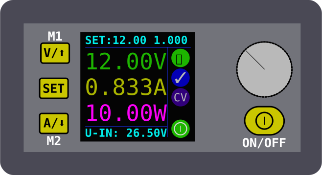
Another versatile type of meter, apart from AC current measurement, are meter modules requiring an external PSU. We studied several types of such meters and classified them based on their applicability for the project. The suitability of the meters was assessed on the basis of voltage and current ranges, accuracy, sample rate, price, and the ease of data collection. In practice, some lab power supplies are also sold as separate PSU and meter modules. There are roughly two types of meters. A DC supply connected meter can be set up to provide one or more channels with different voltage levels to the devices to be measured. The meter channels the power from its own power supply. Some of these meters are powered by standard "brick" power supplies, similar to those used for powering e.g. notebook computers. The meters' output voltage range covers a very wide range of devices to be measured, but is typically slightly smaller than that of laboratory power supplies. To simplify the design, these meters often do not perform DC-DC conversion, and the output voltage range extends to just below the input voltage.
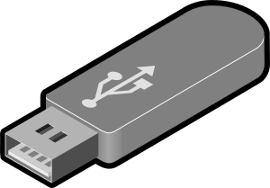
Another common type of meter is the USB power meter, which similarly channels the power and data from the USB bus to the device or devices to be measured. The meter can also provide power from an external PSU instead, but the USB input is usually needed for passing through the data (bidirectional). The USB bus itself also provides a crude method for defining power budgets of devices. The USB power meter is limited to devices equipped with a USB bus, but on the other hand, especially with EU legislation and guidelines, USB has become more common as a general purpose power connector, especially for battery-powered devices. The main challenge for USB is that the latest USB charging and power delivery standards have made USB power distribution more complex, which means that not all USB-based meters are able to measure all new USB devices.
Component modules
There is also a category of component modules which includes both integrated circuits (IC, single components) and circuit boards capable of measuring power. We have excluded simple analog devices such as Hall sensors from this category since they require a number of external components (e.g. ADC, MCU, stable power supply, calibration and temperature compensation circuits) for building a meter. These modules offer a modern alternative to building custom power meters from scratch and avoid time-consuming steps such as circuit design. The integrated circuits also have a very small footprint and often provide integrated digital output which simplifies the reading of data. The combination of such chips and high precision components such as shunt resistors can lead to high quality designs comparable to high-end commercial products.
In the study we identified evaluation boards and circuit boards offered as popular DIY kits, and different types of integrated circuits that come factory calibrated with various logic for reducing noise, voltage and temperature compensation, among other features. During the study, we did an initial search for such component modules from the inventories of popular DIY maker manufacturers such as Adafruit, Seeed Studio, and the Raspberry and Arduino related maker companies. We also went through the catalogs of popular component distributors such as Farnell and Digikey. We then used "snowballing" approach by identifying the ICs and techniques used for measurements and searched for other manufacturers offering products based on the same or similar components listed in the chip makers' product catalogs.
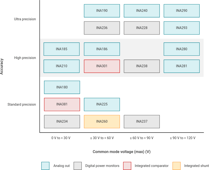
Manufacturers often offer different variations of integrated circuits for different applications. Typical ways of classifying circuits are their operating principle, output format (digital, analog), quantity to be measured (voltage, current, etc.), measurement accuracy, voltage and current ranges, need for additional components (separate inductor, resistor, etc.) or price. For example, Texas Instruments provides the following graph for classifying the devices based on their maximum handling capacity of common mode voltage, the measurement accuracy, and type of meter (analog out, digital, integrated comparator, integrated shunt).
Built-in meters
In addition to the above, many digital devices such as computers and computer components have built-in current meters that provide a software-based API for performing voltage, current, power, and energy measurements. Depending on the system, measurements can be done on a component-by-component basis (e.g. processor, graphics card, solid-state disks, USB devices, screen's backlight) or for the whole system (e.g. total instantaneous power consumption of a laptop).
We plan to publish separate documents on the software-based use of built-in meters at a later stage.
Summary of off-the-shelf power meters
The purpose of the study was to identify available solutions for measuring software power usage in general purpose applications, as well as available commercially available metering hardware that can be utilized without extensive prior knowledge of power measurements. As the cost of precision instruments can be relatively high, especially for small purchases, we have limited our focus to products with a unit price below €100 per channel. The idea of channel-specific refinement is to compensate for possible savings when measuring systems with multiple devices.
After mapping the different types of meters, we found out what different off-the-shelf meters and measurement modules are openly available on the market that can be acquired for in-house use. We used the following criteria:
- The meter is suitable for measuring the consumption of one or more systems selected for the study.
- The meter measures current, power and/or energy, or its output values can be used to derive a value for energy consumption over some period of time.
- The total consumption can be accurately broken down between two time points.
- no PCB design, soldering or other similar equipment manufacturing process is required to implement the meter.
- Meter output values are readable by software and standard protocols (software & hardware, e.g. SCPI), digital output.
- To ensure the scope of the meter mapping work, the price per device is limited to €100 per channel.
| Name | Price | Volt | Amp | Chan | Sample rate | Proto | Target | Accuracy | Other |
|---|---|---|---|---|---|---|---|---|---|
| Hardkernel | |||||||||
| ODROID SmartPower 3 | <50€ | 3 - 18 | 3A | 2 | 200 Hz | USB TTY | MA | documented ascii protocol | |
| - | - | - | 1 | - | - | Discontinued | |||
| - | - | - | 1 | - | - | Discontinued | |||
| Smaller vendors | |||||||||
| Joy-IT JT-UM25C | 100€ | 24V | 5A | 1 | 500 Hz | BT | M | protocol not documented | |
| Powerwerx PWRcheck+ | 250€ | 60V | 40A | 1 | ? | USB TTY | MNAL | protocol not documented, out of stock | |
| <750€ | 6V (!) | 1,5A (!) | 1 | 1 MHz | USB | - | out of stock | ||
| <750€ | 6V (!) | 1A (!) | 1 | 1 MHz | USB | - | out of stock | ||
| Qoitech Otii Arc Pro | 850€ | 5V (!) | 5A | 1 | 4 kHz | USB | M | protocol not documented | |
| Qoitech Otii Ace Pro | 1500€ | 25V | 5A | 1 | 50 ksps | USB | MnA | protocol not documented | |
| Joulescope | 1300€ | 15V | 3A | 1 | 250 ksps | USB | MA | protocol not documented | |
| <2300€ | 1.8 - 8.2 (!) | 3.2A | 1 | 10 kHz | USB | M | Discontinued | ||
| Sistemi P1150 | 1000€ | 17V | 3.2A | 1 | 125 ksps | USB | MA | Not available yet | |
| Lab power supplies | |||||||||
| Owon | |||||||||
| OWON SPS series | 61/31V | 5.1/8.1A | 1 | USB | MnA | SCPI protocol | |||
| OWON SPM series | 60/30V | 10/5A | 1 | USB | MNAl | SCPI protocol | |||
| OWON SPE series | <200€ | 60/30V | 10A | 1 | USB | MNAl | SCPI protocol | ||
| OWON SP series | 60/30V | 10A | 1 | TTY | MNAl | SCPI protocol | |||
| OWON P4000 series | 60/30V | 3/5A | 1 | TTY | MnA | SCPI protocol | |||
| OWON ODP3032 | 30V | 3A | 2 | USB,TTY | MA | SCPI protocol | |||
| OWON ODP3063 | 30+30+6V | 6+6+3A | 3 | USB,LAN,TTY | MA | SCPI protocol | |||
| OWON ODP6033 | 60+60+6V | 3+3+3A | 3 | USB,LAN,TTY | MA | SCPI protocol | |||
| OWON ODP3122 | 30+6V | 12+3A | 2 | USB,LAN,TTY | MA | SCPI protocol | |||
| OWON ODP6062 | 60+6V | 6+3A | 2 | USB,LAN,TTY | MA | SCPI protocol | |||
| Peaktech | |||||||||
| PeakTech P 1565 | 450€ | 16V | 40A | 1 | USB | MAl | protocol not documented | ||
| PeakTech P 1570 | 650€ | 16V | 60A | 1 | USB | MAL | protocol not documented | ||
| PeakTech P 1575 | 450€ | 32V | 20A | 1 | USB | MNAl | protocol not documented | ||
| PeakTech P 1575 | 450€ | 32V | 20A | 1 | USB | MNAl | protocol not documented | ||
| PeakTech P 1585 | 650€ | 32V | 30A | 1 | USB | MNAl | protocol not documented | ||
| Rigol | |||||||||
| Rigol DP711 | 350€ | 30V | 5A | 1 | TTY | MnA | SCPI protocol | ||
| Rigol DP712 | 350€ | 30V | 5A | 1 | TTY | MnA | SCPI protocol | ||
| Rigol DP811 | 700€ | 40/20V | 5/10A | 1 | USB,LAN | MNAl | SCPI protocol | ||
| Rigol DP811A | 850€ | 40/20V | 5/10A | 1 | USB,LAN | MNAl | SCPI protocol | ||
| Rigol DP821 | 700€ | 60+8V | 1+10A | 2 | USB,LAN | M | SCPI protocol | ||
| Rigol DP821A | 800€ | 60+8V | 1+10A | 2 | USB,LAN | M | SCPI protocol | ||
| Rigol DP813 | 750€ | 20/8V | 10/20A | 2 | USB,LAN | MNAl | SCPI protocol | ||
| Rigol DP813A | 900€ | 20/8V | 10/20A | 1 | USB,LAN | MNAl | SCPI protocol | ||
| Rigol DP822 | 750€ | 20+16V | 5+16A | 2 | USB,LAN | MnAl | SCPI protocol | ||
| Rigol DP822A | 900€ | 20+5V | 5+16A | 2 | USB,LAN | MnA | SCPI protocol | ||
| Rigol DP831 | 500€ | 30+30+8V | 2+2+5A | 3 | USB,LAN,TTY | Ma | SCPI protocol | ||
| Rigol DP831A | 750€ | 30+30+8V | 2+2+5A | 3 | USB,LAN | Ma | SCPI protocol | ||
| Rigol DP832 | 400€ | 30+30+5V | 3A | 3 | USB,LAN,TTY | MnA | SCPI protocol | ||
| Rigol DP832A | 600€ | 30+30+6V | 2+2+5A | 3 | USB,LAN | Ma | SCPI protocol | ||
| Rigol DP932E | 550€ | 30+30+6V | 2+2+5A | 3 | USB,LAN | Ma | SCPI protocol | ||
| Rigol DP932U | 650€ | 32+32+6V | 3A | 3 | USB,LAN | MnA | SCPI protocol | ||
| Rigol DP932A | 850€ | 32+32+6V | 3A | 3 | USB,LAN | MnA | SCPI protocol | ||
| Rigol DP2031 | 1350€ | 32+32+6V | 3+3+5A | 3 | USB,LAN | MnA | SCPI protocol | ||
| Joy-IT | |||||||||
| Joy-IT PS360-C | 200€ | 60V | 6A | 1 | USB | MnA | protocol not documented | ||
| Joy-IT PS1440-C | 400€ | 60V | 24A | 1 | USB | MNAl | protocol not documented | ||
| Joy-IT RD6012-C | 200€ | 60V | 12A | 1 | USB | MNAl | protocol not documented | ||
| Joy-IT RD6006-C | 300€ | 60V | 6A | 1 | USB | MnA | protocol not documented | ||
| Twintex | |||||||||
| Twintex PPA100-40A | 40.5V | 10.2A | 1 | USB,LAN | MNAl | ||||
| Twintex DSP-1520 | 15V | 20A | 1 | USB | MNAl | ||||
| Twintex DSP-3210 | 32V | 10A | 1 | USB | MNAl | ||||
| Twintex PPS-1560 | 32V | 10A | 1 | TTY | MNAl | SCPI protocol | |||
| Twintex PPS-1560 | 15.5V | 60.5A | 1 | TTY | MNAL | SCPI protocol | |||
| Twintex PPM-1820 | 19V | 21A | 1 | TTY | MNAl | SCPI protocol | |||
| Twintex TPM-2010E | 20V | 10A | 1 | USB | MNAl | SCPI protocol | |||
| Twintex PPW-2045 | 20.5V | 45.5A | 1 | TTY | MNAL | SCPI protocol | |||
| Circuit board kits | |||||||||
| Adafruit | |||||||||
| Adafruit INA260 | <10€ | 36V | 15A | 1 | I2C | MNAl | |||
| Adafruit INA228 | <15€ | 85V | 10A | 1 | I2C | MNAl | |||
| Adafruit INA3221 | <15€ | 26V | 3.2A | 3 | I2C | MnA | |||
| Adafruit INA219 | <10€ | 26V | 3.2A | 1 | I2C | MnA | |||
| <10€ | 2.7 - 60 | 5A | 1 | Analog | MnA | Analog output only | |||
| <10€ | - | - | - | - | - | Discontinued | |||
| Nordic Semi | |||||||||
| Nordic Semi Power Profiler Kit II | 100€ | 5V (!) | 1A (!) | 1 | 100 kHz | USB | - | ||
| - | - | - | 1 | - | - | Discontinued | |||
| Smaller vendors | |||||||||
| Joy-IT SBC-DVA | 48V | 8A | 1 | I2C | MnA | IC not documented | |||
| Curious Electric ISL28022 | 60V | 32A | 1 | I2C | MnA | IC not documented | |||
| NCD PR3-6 | - | 5A | 8 | I2C | - | Only voltage/current |
Description of categories:
- Price: Retail price for a single unit
- Type: Type of inputs/outputs. DC = general purpose DC meter
- Volt: Supported voltage levels. Not all meters support voltage ranges down to 0 Volts.
- Amp: Maximum sustained current for measurements.
- Chan: Number of channels for measurements
- Sample rate: How many samples can be collected per second. Low (< 1 kHz), medium (1 < x < 100 kHz), high (> 100 kHz)
- Proto: Supported hw/sw protocols for communicates with the meter
- Target: Suitable target devices (SUT) that can be measured with the meter:
- Mobile (5V, >3A), Notebook (20V, >10A), Large computer (12V, >50A), **A **ccessories (12V, >3A)
- m/n/l/a = limited support for this category of devices (5V, >2A) (20V, >3A) (12V, > 10A) (12V, >2A)
Measurement component modules
There are also different kinds of power measurement ICs and circuit boards available as building blocks for the Arduino / Raspberry Pi maker community.
Examples of IC vendors:
- Analog Devices energy metering ICs
- Allegro Microsystems 0-50A current sensors
- Allegro Microsystems 0-400A current sensors
- Allegro Tunneling Magnetoresistance technology
- Cirrus Logic energy measurement
- Microchip Current/Voltage/Power Monitor ICs
- Renesas current sense amplifiers
- Sames energy measurement products
- ST Microsystems metering ICs
- Texas Instruments current-sense amplifiers
Basic theory of digital measurements
A digital power measurement device does not measure power directly. Instead, it measures voltage and current using analog front-end circuitry and ADCs, samples these quantities in time, and calculates power and energy numerically. Consequently, the final measurement is affected by errors from several different stages of the signal chain.
For instantaneous power, $$p (t) = v (t)i (t)$$ and the average power over an interval (T) is $$P = \frac{1}{T}\int_0^T v (t)i (t),dt.$$
For a sampled system, this becomes approximately $$ P \approx \frac{1}{N}\sum_{n=1}^{N} v_n i_n,$$ while energy is obtained by integrating power over time, $$E = \int P (t),dt.$$
This means that errors in either voltage, current, or their timing can propagate into the calculated power. In particular, power measurement is more demanding than simply measuring voltage or current because the two measurements must have sufficiently accurate gain, offset, bandwidth, and relative timing.
Physical measurement errors
The first source of errors is the analog measurement chain used to convert voltage and current into signals suitable for the ADC.
- Shunt resistor value offset: Current is commonly measured using a shunt resistor, with the voltage across the resistor given by (V_ \mathrm{shunt}=IR_\mathrm{shunt}). The actual resistance differs from its nominal value because of manufacturing tolerance. This produces a proportional gain error in the current measurement.
- Shunt resistor temperature and current dependence: The resistance of the shunt changes with temperature. The temperature itself depends on the dissipated power, approximately (P_\mathrm{shunt}=I^2R). At higher currents, self-heating can therefore change the effective shunt resistance and introduce a load-dependent measurement error. The temperature coefficient of resistance (TCR) is consequently important.
- Amplifier input offset voltage: A current-sense amplifier has a finite input offset voltage. This produces an apparent shunt voltage even when the actual current is zero, resulting in a current offset. For low-current measurements, this can be a significant fraction of the measured signal.
- Amplifier gain error and drift: The actual gain differs from its nominal value and can vary with temperature, supply voltage, and time. These effects introduce additional scale-factor errors.
- Common-mode and supply effects: Differential amplifiers and current-sense amplifiers have finite common-mode rejection and power-supply rejection. Variations in the measured voltage or in the device supply can therefore couple into the current measurement.
ADC errors
The ADC introduces both deterministic and stochastic errors. Important specifications include:
- DNL (Differential Non-Linearity): deviation of individual ADC steps from their ideal width. Large DNL can produce missing codes or locally distorted transfer characteristics.
- INL (Integral Non-Linearity): deviation of the overall ADC transfer function from an ideal straight line.
- Gain error: error in the slope of the ADC transfer function after accounting for offset.
- Offset error: displacement of the transfer function from its ideal position.
- Quantization error: finite ADC resolution means that a continuous input must be represented by discrete codes. The resulting quantization error is normally approximately bounded by ±0.5 LSB for an ideal ADC.
- Clipping: signals exceeding the ADC input range are saturated, potentially causing a large and highly nonlinear measurement error.
- Noise: thermal, reference, amplifier, ADC, and digital noise contribute uncertainty to each sample. ADC resolution in bits therefore does not by itself determine the useful measurement resolution; effective number of bits (ENOB) and noise performance are also relevant.
For power measurements, ADC errors in voltage and current should be considered together. For example, a small current offset can cause a substantial error in measured power when the actual load current is small.
Reference errors
The ADC's voltage reference determines the relationship between ADC codes and physical voltage. Reference voltage tolerance, temperature coefficient, noise, long-term drift, and supply sensitivity therefore directly affect the measurement scale.
A reference error is particularly important because it can affect every ADC sample simultaneously. Unlike random noise, it does not necessarily disappear when samples are averaged.
Time-domain errors
Digital measurement systems also have a finite frequency response and a discrete sampling rate. These characteristics determine which parts of the input waveform can be measured correctly.
- Attenuation at higher frequencies: The shunt amplifier, voltage divider, input filtering, ADC input network, and PCB parasitics form an analog frequency response. High-frequency components may therefore be attenuated or phase-shifted before sampling. This matters especially for switched-mode power supplies, where voltage and current can contain substantial switching-frequency and transient components.
- Relative timing / channel skew: For instantaneous power, voltage and current samples must correspond to the same point in time. If the voltage and current channels are sampled at different times, a phase or timing error is introduced. This can be particularly important when measuring rapidly changing signals.
- Sampling jitter: The exact sampling instant varies slightly from sample to sample. Jitter generally becomes more significant as the input frequency increases and can therefore limit the accuracy of measurements containing high-frequency components.
- Aliasing: Frequency components above the Nyquist frequency can be interpreted as lower-frequency components after sampling. Antialiasing filters are therefore required when the input signal contains significant energy above half the sampling frequency. Aliasing is particularly problematic because the resulting error can look like a legitimate low-frequency signal and is therefore not necessarily removed by averaging.
Digital-domain errors
After acquisition, the raw ADC values must be converted into physical quantities and combined to calculate power and energy. Errors can therefore also arise from firmware, numerical processing, and assumptions made by the measurement software.
- Scaling and calibration: ADC codes must be converted into voltage and current using calibration constants. Errors in these constants directly affect the resulting measurement.
- Assumptions about averaging: Averaging can reduce random noise, but it does not generally remove systematic errors such as gain error, offset, reference error, or incorrect calibration. The averaging method also matters: averaging (v) and (i) separately and then multiplying them is not generally equivalent to averaging the instantaneous product (vi). In particular, $$\overline{vi} \neq \overline{v},\overline{i}$$ in general. The difference is related to the correlation between the voltage and current variations. For power measurement, instantaneous multiplication followed by averaging is therefore normally preferable when waveform information is available.
- LUT calculation errors: Lookup tables used for calibration, nonlinear correction, sensor conversion, or other calculations introduce interpolation and quantization errors. The accuracy depends on the table resolution and the interpolation method.
- Numerical precision and rounding: Fixed-point or floating-point calculations introduce rounding and quantization effects. These are usually small compared with analog errors, but can become relevant when integrating energy over long periods or when converting between units.
Latency and temporal alignment
Measurement latency should be distinguished from measurement accuracy. A delayed measurement can still be numerically accurate, provided that the delay is known and does not affect the quantity being calculated.
A typical digital measurement path may contain several stages of latency:
- ADC sampling/conversion: approximately 1 μs
- Firmware buffering: approximately 0.4 ms
- USB buffering: approximately 1–10 ms
- Client-side buffering: approximately 1–10 ms
- Client-side processing and visualization: approximately 16–33 ms
The total displayed latency can therefore be much larger than the ADC conversion time. In addition, different processing paths may introduce different delays between voltage, current, power, and other displayed quantities.
For energy measurements, the more important question is usually not the absolute display latency but whether the samples used in the energy calculation have the correct time interval and temporal alignment.
Other systematic errors
There are several system-level effects that may not be obvious from the ADC specifications alone.
- Correction for voltage drop: A current shunt introduces a voltage drop in series with the load. If the voltage measurement is made on the supply side of the shunt while the current is measured through the shunt, the measured voltage may differ from the actual load voltage. Depending on the measurement topology, the firmware may need to compensate for this drop.
- Measurement amplifier supply current: The measurement circuitry itself consumes power. For example, the supply current of the current-sense amplifier contributes to the total current drawn from the source if the amplifier is powered from the measured supply. Whether this current should be included or excluded depends on what quantity the measurement is intended to represent.
- Ground and wiring effects: PCB traces, connectors, cables, and ground connections have finite resistance and inductance. Voltage drops and ground offsets can therefore become part of the measurement, particularly at high currents or during fast transients.
- Crosstalk: Voltage and current measurement channels can couple into one another through PCB traces, power supplies, amplifier inputs, or ADC multiplexing. This can create errors that depend on the waveform being measured.
- Calibration and reference conditions: Calibration is only valid within the conditions under which it was performed. Temperature, supply voltage, measurement range, and frequency can all affect the result. A single-point calibration may correct an offset but cannot generally correct gain error or nonlinearities over the full operating range.
Measurement methodology
The measurement result should therefore be considered together with the conditions under which it was obtained. A useful characterization of a digital power measurement device should specify at least:
- What is being measured — source power, load power, shunt power, or some other quantity.
- Voltage and current ranges and the corresponding ADC ranges.
- Sampling frequency and effective bandwidth.
- Whether voltage and current are sampled simultaneously or sequentially.
- Analog filtering and antialiasing.
- Calibration procedure and calibration conditions.
- Averaging/integration interval used to calculate displayed power and energy.
- Expected waveform characteristics, including DC, mains-frequency, switching-frequency, and transient components.
- Temperature and operating conditions.
- Uncertainty or error specification, rather than only nominal ADC resolution.
A particularly useful test methodology is to compare the device against a traceable reference under several controlled conditions: zero input for offset, known DC voltage/current for gain accuracy, different current levels for shunt and amplifier linearity, different temperatures for thermal drift, and representative dynamic waveforms for bandwidth, timing, and aliasing. Measurements should ideally be repeated at several points across the operating range rather than relying on a single calibration point.
For energy measurement, the reference should also be compared over a sufficiently long and well-defined integration interval. Short measurements can be dominated by timing, startup transients, and quantization effects, whereas longer measurements can expose accumulated integration and calibration errors.
Overall, the useful accuracy of a digital power meter is therefore determined by the entire measurement chain, not by the ADC resolution alone. A device with a high-resolution ADC can still produce inaccurate power or energy measurements if the shunt, amplifier, reference, sampling architecture, calibration, or numerical processing introduces larger errors.
| Error source | Primarily affects | Typical character | Effect on power | Effect on energy |
|---|---|---|---|---|
| Shunt resistance tolerance | Current | Systematic gain error | Proportional error | Proportional error |
| Shunt TCR / self-heating | Current | Load- and temperature-dependent | Gain changes with current | Accumulated if operating point changes |
| Shunt parasitic inductance | Current | Frequency-dependent | Amplitude/phase error | Usually small for DC, potentially significant for fast transients |
| Amplifier gain error | Current | Systematic | Proportional error | Proportional error |
| Amplifier input offset | Current | Systematic offset | Particularly important at low current | Can accumulate significantly |
| Amplifier offset drift | Current | Temperature/time dependent | Variable offset | Accumulating error |
| Amplifier noise | Current | Random | Noise in instantaneous power | Reduced by averaging/integration |
| Common-mode rejection | Current | Signal-dependent | Can create waveform-dependent error | Depends on waveform |
| ADC gain error | Voltage/current | Systematic | Proportional error | Proportional error |
| ADC offset error | Voltage/current | Systematic | Offset-related error | Can accumulate |
| ADC INL | Voltage/current | Nonlinear | Level-dependent error | Level-dependent |
| ADC DNL | Voltage/current | Nonlinear | Usually small, potentially code-dependent | Usually small |
| Quantization | Voltage/current | Deterministic/noise-like | More visible at low signals | Partly averaged |
| ADC noise | Voltage/current | Random | Instantaneous noise | Usually reduced by integration |
| ADC clipping | Voltage/current | Severe nonlinear error | Potentially very large | Potentially very large |
| Reference voltage error | ADC scale | Systematic | Gain error | Gain error |
| Reference drift/noise | ADC scale | Temperature/random | Variable gain/noise | Variable/accumulated |
| Analog bandwidth | V/I | Frequency-dependent | Amplitude error | Depends on waveform |
| Analog phase shift | V/I | Frequency-dependent | Power-factor / waveform error | Can affect energy |
| Anti-aliasing filter | V/I | Frequency-dependent | Can attenuate real signal | Can bias energy |
| Aliasing | V/I | Nonlinear sampling artifact | Potentially large | Potentially large |
| Sampling-rate error | Time base | Systematic | Usually indirect | Direct energy/integration error |
| Sampling jitter | Time | Random | More important at high frequency | Usually averages somewhat |
| Voltage/current channel skew | V vs. I | Systematic timing error | Can be significant for AC/high-frequency signals | Can bias integrated energy |
| Channel-to-channel gain mismatch | V vs. I | Systematic | Power gain error | Energy gain error |
| Channel-to-channel offset mismatch | V vs. I | Systematic | Low-load error | Can accumulate |
| Calibration uncertainty | Entire chain | Systematic + uncertainty | Sets achievable accuracy | Sets achievable accuracy |
| Calibration temperature dependence | Entire chain | Environmental | Operating-point dependent | Operating-point dependent |
| LUT/interpolation error | Digital processing | Deterministic | Small nonlinear error | Small nonlinear error |
| Numerical rounding | Digital processing | Deterministic | Usually negligible | Can accumulate over very long integrations |
| Incorrect averaging method | Digital processing | Algorithmic | Can produce systematic error | Can produce systematic error |
| Incorrect RMS/power calculation | Digital processing | Algorithmic | Potentially large | Potentially large |
| Energy integration/time-base error | Digital processing | Systematic | — | Direct energy error |
| Firmware overflow / saturation | Digital processing | Severe nonlinear | Potentially large | Potentially large |
| Buffering / latency | System timing | Delay | Usually no effect on steady-state power | Can matter for event-based measurements |
| Voltage-drop compensation | System | Model-dependent | Systematic | Systematic |
| Measurement circuit consumption | System | Systematic | Depends on measurement definition | Depends on measurement definition |
| Ground/wiring resistance | Physical setup | Load-dependent | Voltage/current error | Energy error |
| Ground loops / common impedance | Physical setup | Setup-dependent | Can introduce offsets/noise | Can introduce offsets/noise |
| Crosstalk | Physical setup | Signal-dependent | Waveform-dependent | Waveform-dependent |
| Connector/contact resistance | Physical setup | Load-dependent | Particularly at high current | Energy error |
| EMI / conducted noise | Physical setup | Random/systematic | Can contaminate samples | May average out—or alias |
| Temperature gradients | Physical setup | Environmental | Drift / thermal EMFs | Long-term error |
| Startup/transient behavior | System | Time-dependent | Important for short measurements | Important if integration starts/stops near transient |
Next step: Software-Based Meters and Measurement software
The next analysis section covers the Software-Based Meters and Measurement software.