


Simple example setup
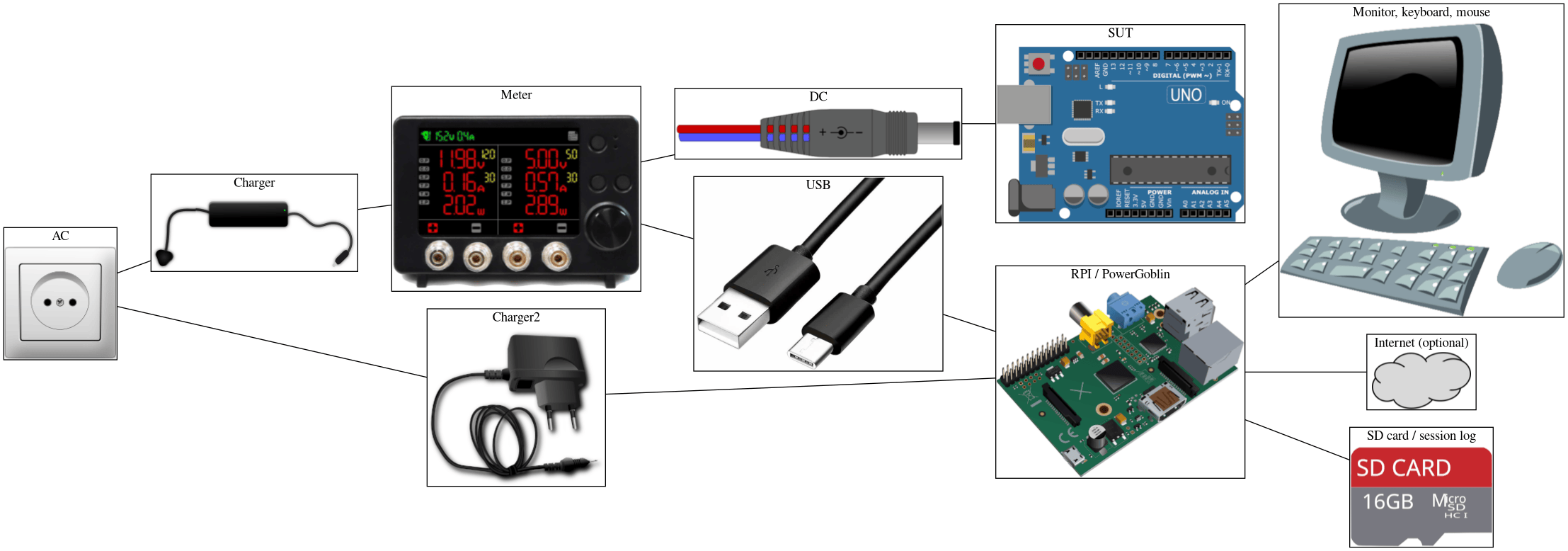
The following simple hardware configuration is suitable for learning how to use PowerGoblin. The goal of the setup is to measure the power consumption of an Arduino-based microcontroller with PowerGoblin when it is installed on the Raspberry Pi computer shown in the figure.
Of course, PowerGoblin also supports much more complex hardware configurations such as the measurement laboratory in University of Turku. This basic configuration contains all the necessary components for running a successful measurement session.
Components
Let's now look in more detail at the role of each component in the figure.
Chargers
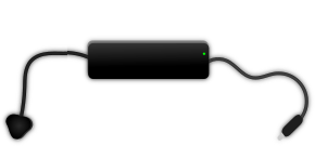
The Hardkernel's 19V/7A charger provides power for the SmartPower 3 meter, and the two devices connected to channels 1 and 2.
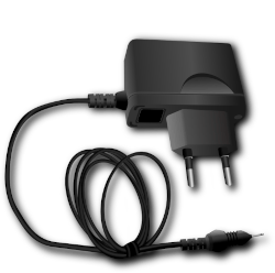
The generic 5V USB-C charger powers the Raspberry Pi. We recommend buying a kit which includes an official charger. Other chargers may not provide enough current, which can affect the stability of the system.
Power meter

The SmartPower 3 meter measures the voltage, current, and power of the devices connected to any of the two output channels. The DC input (charger) and USB data link ports are located on the opposite sides.
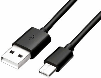
The USB-A -- USB-C cable connects the meter to the Raspberry Pi. A USB-C -- USB-C cable works as well if the Raspberry Pi has USB-C ports.
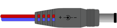
The DC plug powers the SUT. Make sure that you connect the color coded wires correctly to the power meter. Usually the plus wire / banana connector is encoded with red color and the minus with blue or black color. Reversing the wires may destroy the SUT (unless it has reverse polarity protection) and even start a fire!
SUT
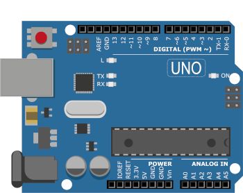
It is probably best to program the SUT before doing any measurements and while performing measurements, the reprogramming phase and measurement phase should be completely isolated to avoid potential damage to the devices.
The board is powered with a DC cable connected to the DC connector (alternatively the board can be powered via USB as well). If you wish to simultaneously program the SUT via USB, the SUT may draw power through the USB and the measurement result will be incorrect. Also be careful not to allow the SUT to form ground loops, e.g. through the GPIO pin connections. In the worst case, incorrect connections can damage the meter and/or the SUT!
RPI
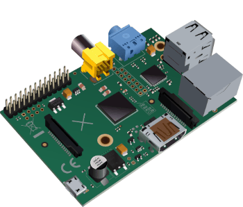
The Raspberry Pi acts as a standard environment in which to run the PowerGoblin software. The software installation section contains more recommendations for choosing the Raspberry Pi model.

The device can be connected to the internet, for example to download the PowerGoblin distribution. Another option is to transfer the programs, e.g. on a USB memory stick.

Collected measurement data can be read from the memory card. Since the device usually runs Linux, you will need a system that can read Linux file systems, or a partitioning (e.g. a FAT32 partition) that is readable by other systems, as well. Another option is to transfer the data, e.g. on a USB memory stick.

The need for input and output devices is probably obvious if the measurements are not done over the network.
Configuring the hardware
Make sure that the SmartPower 3 meter has been configured properly. To avoid damaging the SUT, disconnect the DC plug before doing this, and reconnect it when done.
- Press the topmost button to launch the configuration menu
- Use the large round rotary switch to navigate the menu
- The rotary switch also supports 'clicking' to select / toggle items.
- Select a serial baud rate of
115200 bps(should be the default value). - Select a logging interval of
10 ms(should be the default value). - Make sure that the document icon in the top right corner is bright green (= logging via USB is on).
- Return to the main view (topmost button)
- Select the voltage for the output channel:
5,0 V - Select the max current for the output channel:
3,0 A - Make sure the channels are offline (numbers next to the configured A/V values are gray, not red)
Reconnect the SUT.
Now the channels can be toggled online by pressing the two buttons in the middle. You should toggle the power only via these buttons to avoid destroying the SUT with inductive voltage spikes!
Next step: Obtaining the software
Please continue to the next phase for further instructions on obtaining the PowerGoblin software and installing it.